

Ipari hírek


Ipari hírek
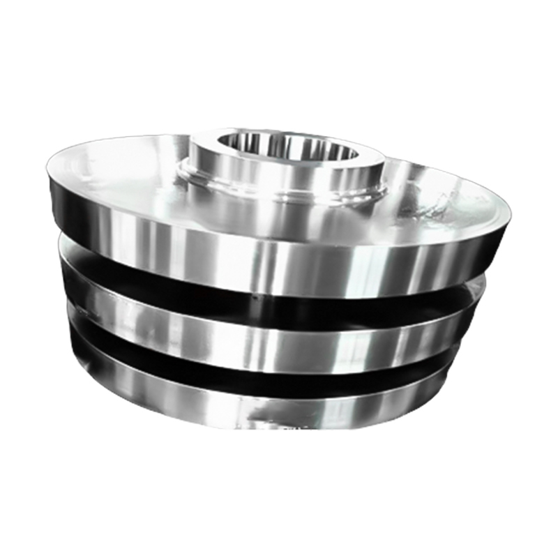
How do Wind Turbine Gearbox Forgings work?
2026-06-12
Wind turbine gearbox forgings are precision-engineered metal components produced through controlled deformation of high-grade alloy steel, designed specifically to transmit and amplify rotational forces within a wind turbine's drivetrain. In simple terms, they are the structural backbone of the gearbox — converting the slow, high-torque rotation of the rotor blades into the faster shaft speed required by the electrical generator.
A modern multi-megawatt wind turbine rotor turns at roughly 5 to 15 RPM, while the generator requires input speeds of 1,000 to 1,800 RPM. The gearbox bridges this gap through a series of gear stages, and every gear, shaft, ring gear, and planet carrier in that assembly must withstand enormous cyclic loads over a design life of 20 years or more. Forgings deliver the grain-refined microstructure and mechanical integrity that cast or machined-from-bar alternatives simply cannot match at this scale.
The Role of the Gearbox in Wind Energy Conversion
To appreciate why forging quality matters, it helps to understand the mechanical demands placed on a wind turbine gearbox. The drivetrain must handle:
- Continuous variable torque as wind speed fluctuates unpredictably
- Sudden torque spikes during grid faults or emergency stops
- Bending and torsional loads transmitted from the rotor hub
- Thermal cycling between cold start-up and operational temperatures
- Billions of fatigue load cycles across the turbine's service life
A single planetary gear stage in a 3 MW turbine gearbox can experience peak tangential forces exceeding 500 kN. Only components with a refined, homogeneous internal structure — achievable through forging — can sustain these conditions without crack initiation or premature failure.
Key Components Produced by Forging
Not every part of a wind turbine gearbox is forged, but the most structurally critical ones are. The following components are routinely manufactured as forgings:
| Component | Function | Typical Material |
|---|---|---|
| Planet Carrier | Supports planet gears and transmits torque in planetary stages | 18CrNiMo7-6 / 42CrMo4 |
| Ring Gear Blank | Outer gear housing for planetary stage meshing | 42CrMo4 / 34CrNiMo6 |
| Hollow Input Shaft | Connects main rotor shaft to first gear stage | 34CrNiMo6 / 30CrNiMo8 |
| High-Speed Output Shaft | Delivers rotational energy to the generator | 18CrNiMo7-6 |
| Helical Gear Blank | Intermediate and high-speed gear stage power transmission | 18CrNiMo7-6 |
| Gearbox Housing Flange | Structural interface between gearbox and nacelle frame | 42CrMo4 / Structural alloy steel |
Material Selection for Gearbox Forgings
Material choice is the first critical decision in producing a reliable gearbox forging. The grade must satisfy multiple, often competing requirements simultaneously: high hardenability for deep case-hardening, sufficient core toughness to resist impact loads, fine austenitic grain size for fatigue resistance, and weldability or machinability for downstream processing.
Preferred Alloy Grades
The industry has converged on a relatively short list of proven alloy steels:
- 18CrNiMo7-6 — the most widely used case-hardening steel for gear blanks; achieves surface hardness of 58–62 HRC after carburizing and case-hardening while retaining a tough core with Charpy impact values above 60 J at −40 °C.
- 42CrMo4 — a quench-and-temper steel favored for shafts and carriers requiring uniform through-section strength; typical tensile strength of 1,000–1,200 MPa after heat treatment.
- 34CrNiMo6 — preferred for large-diameter input shafts where cross-section hardenability is critical; excellent fatigue limit of approximately 550 MPa.
- 30CrNiMo8 — used for the most demanding large forged shafts in multi-megawatt platforms, with yield strength commonly exceeding 900 MPa.
Cleanliness and Inclusion Control
Steel cleanliness is equally important. Wind gearbox forgings typically require vacuum degassing (VD) or vacuum arc remelting (VAR) to reduce hydrogen content below 2 ppm and sulfur below 0.010%. Non-metallic inclusion ratings must comply with standards such as ISO 4967 or ASTM E45, since even small alumina or sulfide stringers act as fatigue crack initiation sites under high-cycle loading.
The Forging Process Step by Step
The forging of gearbox components follows a carefully controlled sequence. Each stage contributes to the final mechanical properties of the part.
1. Ingot or Billet Preparation
Starting stock is typically a continuous cast billet or a vacuum-degassed ingot. For large components like planet carriers weighing over 1,000 kg, ingots are preferred to ensure chemical homogeneity. The ingot top (pipe zone) and bottom (segregation zone) are cropped and discarded to ensure only clean, homogeneous material enters the forging process.
2. Heating and Soaking
The billet is heated in a gas-fired or electric furnace to the forging temperature range, typically 1,100–1,250 °C for low-alloy steels. Soaking time is calculated based on section thickness to ensure uniform temperature throughout the cross-section, preventing temperature gradients that would cause non-uniform deformation and residual stress.
3. Open-Die or Closed-Die Forging
Depending on part geometry and production volume, either open-die (free forging) or closed-die (impression die) forging is used:
- Open-die forging is standard for large shafts and discs. Press forces range from 20 MN to 125 MN for the heaviest wind gearbox components. Multiple passes with progressive reduction ratios refine the grain structure and close internal voids.
- Closed-die forging suits near-net-shape production of smaller, geometrically complex parts such as planet gear blanks, reducing material waste and subsequent machining allowance.
The forging ratio — the ratio of initial to final cross-sectional area — is a key process parameter. Industry practice for wind gearbox forgings typically requires a minimum forging ratio of 4:1 to 6:1 to ensure adequate grain refinement and the elimination of as-cast dendrite structure.
4. Controlled Cooling
After forging, parts are cooled under controlled conditions. Rapid or uncontrolled cooling can introduce quench cracking or residual hydrogen-induced defects in alloy-steel forgings. Most large forgings are placed in insulating boxes or slow-cooled in furnaces at programmed rates of 20–50 °C/hour down to below 300 °C.
Heat Treatment: Unlocking Full Mechanical Potential
Forging alone refines grain structure, but heat treatment is what achieves the target mechanical property profile. Wind gearbox forgings undergo one or more of the following heat treatment routes:
Normalizing and Annealing
Applied immediately after forging to relieve forging stresses, homogenize the microstructure, and improve machinability before final heat treatment. Normalizing is performed at 850–920 °C, followed by air cooling.
Quenching and Tempering (Q&T)
For through-hardened components such as shafts and carriers, austenitizing at 840–880 °C is followed by oil or water quenching to form a martensitic structure, then tempering at 550–650 °C to achieve the target combination of strength and toughness. This process yields tensile strengths in the range of 900–1,200 MPa with good notch toughness.
Case Hardening (Carburizing + Quenching)
Gear blanks made from case-hardening steels like 18CrNiMo7-6 are processed in carburizing furnaces at 880–980 °C in a carbon-rich atmosphere for many hours, building up a carbon-enriched surface layer of 0.8–2.5 mm depth. After carburizing, quenching and low-temperature tempering (150–200 °C) produce a case hardness of 58–62 HRC with compressive residual stresses that significantly enhance the fatigue strength of the tooth root and flank.
Induction Hardening
Shaft journals and bearing seats are often selectively induction-hardened to achieve localized surface hardness of 54–62 HRC while preserving core toughness. This is especially practical for large shafts where full case carburizing would be impractical.
Why Forging Outperforms Casting for Gearbox Components
The mechanical advantages of forging over casting are well-documented in metallurgical literature and field failure analysis. The differences are especially pronounced under the fatigue-dominated loading conditions that wind gearbox components experience:
- Fatigue strength: Forgings typically exhibit fatigue limits 20–30% higher than comparable castings of the same alloy, due to the elimination of porosity and the alignment of grain flow with the stress direction.
- Impact toughness: The unbroken grain flow in forgings gives Charpy impact values that can exceed those of castings by a factor of 2 to 3 at low temperatures, crucial for offshore wind turbines operating in arctic conditions.
- Dimensional consistency: Controlled die forging achieves tighter dimensional tolerances, reducing subsequent machining time and material removal.
- Surface integrity: The deformed, compressed surface of a forging is inherently more resistant to surface fatigue, pitting, and micro-crack initiation than a cast surface.
| Property | Forging | Casting |
|---|---|---|
| Grain Structure | Refined, aligned with part geometry | Coarse dendritic, random orientation |
| Internal Porosity | Eliminated during deformation | Inherent shrinkage porosity risk |
| Tensile Strength | 900–1,200 MPa (alloy Q&T) | 600–900 MPa (typical structural cast) |
| Fatigue Limit | Higher by 20–30% | Baseline |
| NDE Reliability | High (uniform structure) | More complex (gas pores, shrinkage) |
Precision Machining After Forging
Forgings arrive as rough-shaped near-net components and must be finish-machined to exact engineering tolerances before assembly. The machining stages include:
- Rough turning and milling to remove forging scale and bring external dimensions within rough machining tolerances
- Gear tooth cutting by hobbing or shaping, followed by shaving or grinding to achieve tooth profile accuracy classes of ISO 5 or better
- Hard turning and cylindrical grinding of bearing journals to achieve surface roughness values of Ra 0.4–0.8 µm and roundness tolerances within 5 µm
- Gear tooth grinding after case-hardening to correct thermal distortion and achieve final profile and lead tolerances
- Shot peening of gear tooth roots to introduce beneficial compressive residual stresses, extending fatigue life by 15–25%
The integrated combination of forging, heat treatment, and precision machining within a single production organization — as practiced by comprehensive heavy industrial manufacturers — is critical for maintaining quality chain continuity and minimizing inter-process handling damage.
Quality Inspection and Non-Destructive Evaluation
Given the safety-critical nature of wind gearbox forgings, comprehensive inspection is mandatory at multiple production stages. The standard inspection sequence includes:
- Ultrasonic Testing (UT) — performed on the rough forging to detect internal discontinuities such as pipe remnants, hydrogen flakes, or segregation bands. Acceptance criteria typically follow EN 10228-3 or ASTM A388.
- Magnetic Particle Inspection (MPI) — applied to detect surface and near-surface cracks after final machining and heat treatment.
- Hardness Testing — Brinell or Rockwell measurements confirm that the heat treatment has achieved the specified hardness range across the cross-section.
- Mechanical Property Testing — witness test coupons taken from forging extensions (prolongations) are tested for tensile strength, yield strength, elongation, reduction of area, and Charpy impact energy, usually at both ambient temperature and −40 °C.
- Dimensional and Gear Metrology — coordinate measuring machines (CMM) and gear analysis machines verify that all dimensional tolerances, including tooth profile, helix angle, pitch, and runout, are within drawing specification.
- Surface Roughness and Case Depth Verification — ensures carburized layers meet the specified effective case depth and surface hardness requirements.
Full traceability documentation accompanies every forging, from melt heat number and chemical composition certificate through to final inspection records, enabling complete audit trails required by wind turbine certification bodies.
Installation Guidance for Wind Gearbox Forgings
Even the highest-quality forging can underperform if installed incorrectly. The following installation best practices apply to gearbox shaft and gear assemblies:
- Cleanliness: All mating surfaces, keyways, splines, and bearing housings must be thoroughly cleaned and degreased before assembly. Contamination particles as small as 20 µm can cause fretting damage on interference-fit joints.
- Interference fits: Shrink-fit components should be heated to 80–120 °C above ambient (typically using induction heating tools or controlled ovens) to achieve the required thermal expansion before assembly. Flame heating is not acceptable as it causes local metallurgical damage.
- Torque and preload: All fasteners should be tightened to specified torque values using calibrated torque tools. Hydraulic bolt tensioning is preferred for large-diameter flange bolts to ensure even preload distribution.
- Alignment: Shaft coupling alignment must be verified with dial indicators or laser alignment tools to ensure parallelism and angular alignment within the manufacturer's specified tolerance, typically within 0.05 mm/m.
- Lubrication: The correct grade of synthetic gearbox oil (typically ISO VG 320 or ISO VG 460) must be used at the recommended fill level, and the first oil change is typically scheduled within the initial 500–1,000 operating hours to flush break-in wear particles.
Common Fault Modes and Diagnostic Approaches
Understanding the failure modes of gearbox forgings enables proactive maintenance planning. The most frequently encountered fault modes are:
Gear Tooth Fatigue (Pitting and Spalling)
Contact fatigue manifests as surface pitting on the pitch line of gear teeth, eventually progressing to spalling where larger flakes of case-hardened material break away. Causes include overloading, lubricant film breakdown, and inadequate case hardness depth. Vibration spectrum analysis typically reveals gear mesh frequency sidebands before visual damage is detectable.
Bending Fatigue at Tooth Root
Cyclic bending stresses at the tooth root can initiate fatigue cracks, especially if the case depth is insufficient, the root geometry is not properly ground, or abnormal dynamic loads have been experienced. Root cracks propagate quickly and can cause catastrophic tooth fracture. Oil debris particle analysis (ferrography) detecting chunks larger than 50 µm in the lubrication circuit is an early warning sign.
Shaft Fatigue Cracking
Shafts are susceptible to fatigue cracking at stress concentration features such as keyways, snap ring grooves, and shoulder fillets. Proper fillet radius sizing (typically R ≥ 2 mm at critical transitions) and shot-peening of keyways are standard mitigation measures in modern designs.
Bearing Race Fretting and Spalling
Planet gear bearings and main shaft bearings are high-wear items. Bearing race spalling generates characteristic high-frequency vibration signatures detectable by accelerometers. Condition monitoring systems sampling at rates above 20 kHz can identify early bearing distress weeks before failure escalates.
Diagnostic Tools
Modern wind turbines integrate continuous condition monitoring systems (CMS) that log:
- Vibration spectra from accelerometers on the gearbox housing
- Oil temperature, viscosity, and debris particle count
- Acoustic emission signals from bearing races
- Torque and rotational speed data from SCADA systems
When anomalies are detected, field borescope inspection of gear tooth surfaces and oil sampling for spectrometric analysis can confirm and characterize the defect before a planned replacement is scheduled, avoiding unplanned downtime costs that can reach €50,000 to €200,000 per incident for offshore installations.
How Forging Quality Directly Impacts Wind Energy Efficiency
The connection between forging quality and wind farm energy yield is direct and quantifiable. A gearbox that operates reliably and efficiently contributes to turbine availability, which is the primary driver of annual energy production (AEP).
Industry benchmark data indicates that gearbox failures account for approximately 10–20% of unplanned wind turbine downtime, with average repair times of 5 to 14 days depending on crane availability and component lead times. For a 3 MW turbine operating at a 35% capacity factor, a single week of unplanned gearbox downtime represents approximately 588 MWh of lost generation.
Beyond availability, gearbox mechanical efficiency is directly tied to power transmission losses. High-quality forged and precision-ground gear sets operating with optimal surface finish and tooth geometry can achieve helical stage efficiencies above 99.5% per mesh. For a three-stage gearbox, this results in an overall transmission efficiency of approximately 98.5%, maximizing the conversion of rotor kinetic energy into electrical output.
This is why serious wind turbine manufacturers and OEM gearbox suppliers specify forged components with precise metallurgical and dimensional requirements — the investment in forging quality is recovered many times over through extended service life and reduced lifecycle maintenance costs.
ACE Group: Integrated Wind Turbine Gearbox Forging Manufacturing
ACE Group is a comprehensive enterprise group with a focused presence in the heavy industrial manufacturing sector, operating as a dedicated Wind Turbine Gearbox Forgings Supplier. The company's integrated business model spans forging, heat treatment, precision machining, welded structures, and heavy-duty power-and-free chain spraying production — covering the complete core manufacturing processes required for industrial machinery components.
This integrated layout is a significant operational advantage in the wind energy supply chain. By controlling forging, heat treatment, and precision machining under a single organization, ACE Group eliminates inter-facility handling risks, maintains continuous quality chain traceability, and can optimize the processing sequence for each specific component — from initial forging parameter selection through to final dimensional inspection and certification.
The combination of technological expertise and large-scale production capability positions ACE Group to serve global wind turbine gearbox OEMs and Tier 1 suppliers requiring consistent, certified forging supplies for multi-megawatt turbine platforms.


Hírek
Üzenjen nekünk most!
-
Mobil terminál
-
Gyors linkek
Termékek Rólunk Felszerelés és kapacitás Minőség Hírek Lépjen kapcsolatba velünk -
Termékkategória
Elektromos energia kovácsolás Hajó- és kikötői gépek kovácsolása Bányászati és Kohászati Kovácsoltvas Élelmiszer- és takarmányipari gépek kovácsolása Petrolkémiai ipari kovácsolás Hegesztés gyártása TESTRE SZÁMÍTOTT BEFEJEZÉSI ALKATRÉSZEK -
Lépjen kapcsolatba velünk
Mob.: +86-173 7218 0878 Tel.: +86-515-8389 0396 E-mail: ivy.zhai@aceprocess.cn Add.: No.21 Jinfeng Road, Gazdaságfejlesztési Park, Dafeng District, Yancheng City, Jiangsu, Kína
Szerzői jog © 2025 Yancheng ACE Machinery Co., Ltd. Minden jog fenntartva.
Kínai nyitott kovácsoltvas gyártó
egyedi precíziós kovácsolás szállítója
